Gabe's Gadgets
40m QRP Transceiver - CW to AM Conversion
In its unmodified state, the NorCal 40A is a CW radio transceiver that operates on the 40m (7 MHz) band. It is easy to assemble, simple in operational theory, and highly hackable. Despite being a relatively primitive and inflexible platform for communication by modern standards, for these reasons the 40A has served well as a learning platform for many students and hobbyists.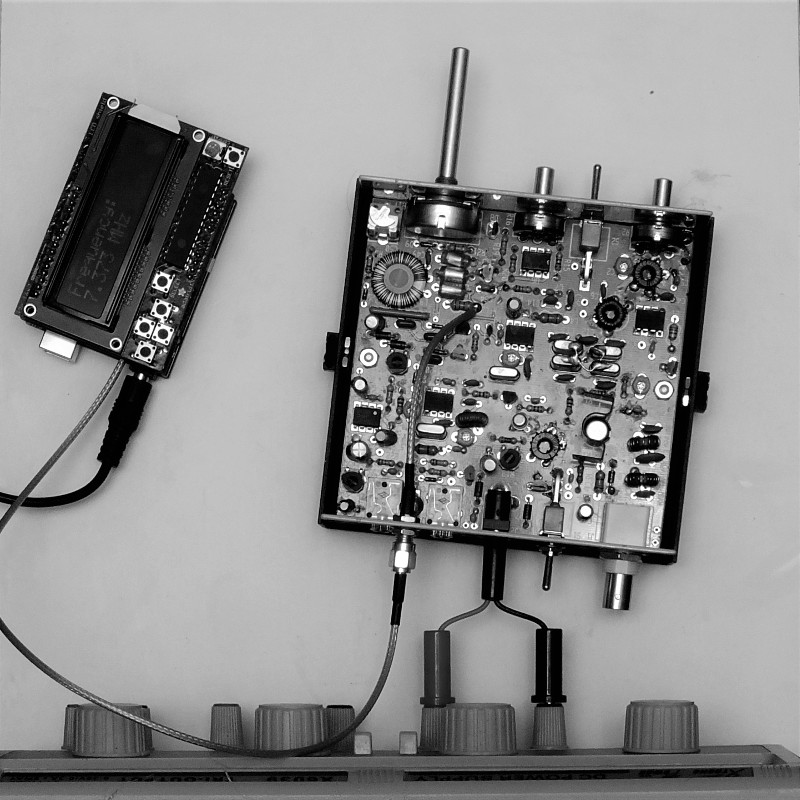
When the NorCal 40A was released in 1999, proficiency with Morse Code was a requirement for obtaining any class of amateur radio licence. Therefore, the relative simplicity of an CW transceiver was seen as lowering the barrier to entry for new HAMs rather than raising it. Because the Morse Code section of the amateur radio licensure exam was eliminated in 2008, it now makes more sense to get students started with radio on a slightly more complex transceiver capable of phone (speech audio) transmission and reception.
Basics:
Continuous wave (CW) radios communicate using single-frequency signals. Rather than encoding information within the wave itself, such radios use the mere presence (or absence) of a signal to represent data. Unlike a CW signal which cannot carry analog information, amplitude-modulated (AM) signals can carry plain speech. AM transmitters work by sending out radio waves with continuously varying strengths.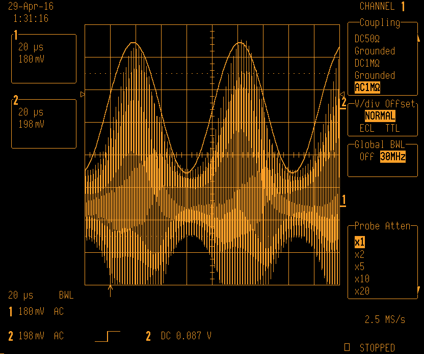
Unmodified CW Transceiver Operation:
Below, the individual subsystems are described in the direction of signal flow (indicated by arrows).
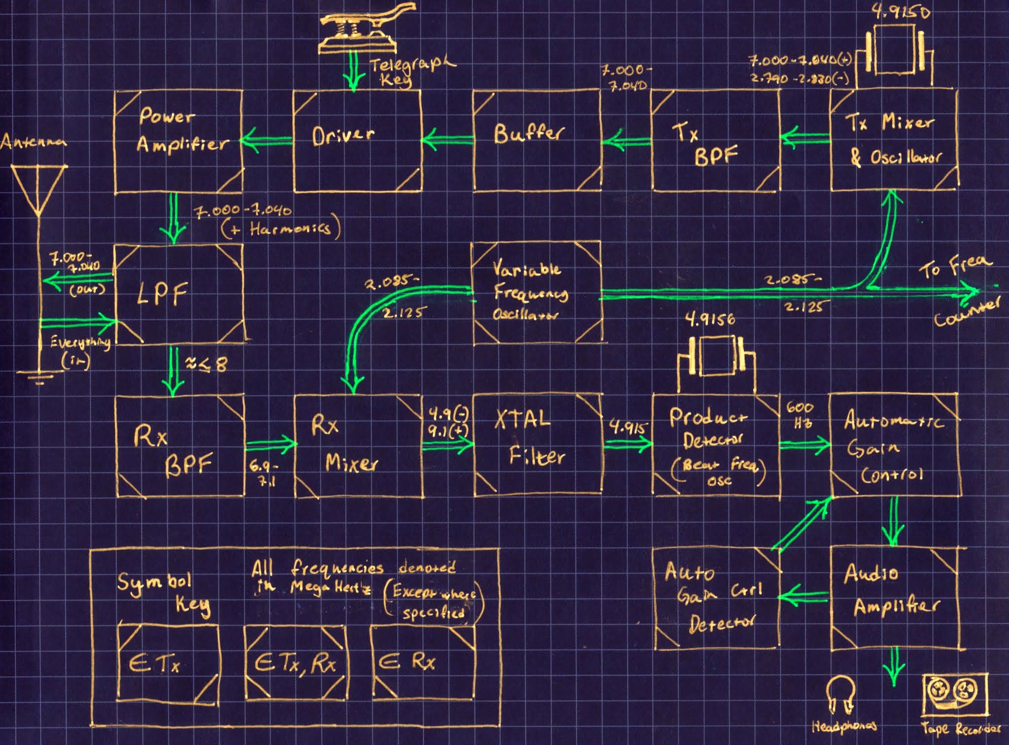
- Variable Frequency Oscillator
- Provides variable frequency (2.085 to 2.125 MHz) for tuning of radio.
- Provides signal to both receiver and transmitter.
- Frequency variability is what allows for radio to be tuned.
- When mixed with the signal produced by the Tx Mixer and Oscillator (4.915 MHz), the VFO signal’s frequency is shifted into the range of 7.000 to 7.040 MHz.
- When mixed with the filtered signal that is received from the antenna, the VFO signal’s frequency is shifted to approximately 4.9 MHz.
- Tx Mixer & Oscillator
- Utilizes a crystal to produce a signal with a frequency of precisely 4.915 MHz.
- Mixes the above mentioned signal with that produced by the VFO.
- This results in a signal with a frequency in the range of 7.000 to 7.040 MHz which is later amplified, modulated, and transmitted.
- Also produces a frequency in the range of 2.7 MHz. This component is not desired and is later filtered out in the Tx Band Pass Filter that follows this block.
- Tx Band Pass Filter
- Removes the undesired 2.7 MHz component of the signal produced by the Tx Mixer and Oscillator.
- Passes the desired 7 MHz range component to the Buffer with minimal attenuation.
- Buffer
- Consists of a few passive components and a single JFET.
- Isolates the signal generating blocks of the transmitter chain from the amplification blocks that follow.
- Driver
- Modulates the signal passed from the buffer according to the state of the attached telegraph key
- A connection across the contacts of J3 results in transmission of the buffered 7 MHz (range) signal to the Power Amplifier
- Lack of a connection between the contacts of J3 results in great attenuation of the above mentioned signal
- Power Amplifier
- Common emitter type amplifier based around the 2N3553 NPN transistor (Q7).
- Provides power amplification to a signal that is transmitted by the Driver block.
- Incoming current is stepped up (3.5x) by transformer T3.
- Incoming voltage is stepped down by the same ratio by T3.
- T3 also isolates the base of Q7 from the DC power supply. (The magnetic field produced by a DC current is static and can therefore not induce an electric current.)
- Low Pass Filter
- Greatly attenuates harmonics produced by non-linearities in the amplification chain of the transmitter.
- Greatly attenuates frequencies above approximately 8 MHz that will “confuse” the receiver chain.
- Rx Band Pass Filter
- Greatly attenuates all the components of the signal received by the antenna that are not in the range of 7.000 ± 0.100 MHz.
- Allows for coarse adjustment of RF Gain by the adjustment of potentiometer R2.
- Rx Mixer
- Combines the frequency produces by the VFO with the signal passed by the Rx Band Pass Filter to create a signal with two components. Those components are at frequencies of 4.9 MHz (desired) and 9.1 MHz (not desired).
- Crystal Filter
- Very high-Q filter intended to remove virtually all components of the mixed signal that are not at precisely 4.9150 MHz.
- Product Detector (Beat Frequency Oscillator)
- Mixes the 4.9150 MHz signal received from the Crystal Filter with a 4.9156 MHz produced by a crystal oscillator.
- This results in heterodyning which produces a signal of 600 Hz (mid-sonic region)
- Automatic Gain Control
- Compensates for variability in amplitude of received signals by adjusting RF gain accordingly
- Audio Amplifier
- Amplifies the signal that it receives from the Automatic Gain Control block to one with enough power to drive a pair of stereo headphones.
- Automatic Gain Control Detector
- Feedback circuit utilized to modulate the gain of the Automatic Gain Control block.